You should see brightening followed by dimming on the LED.
#ARDUINO PWM CODE#
The code is given below − Example int led_pwm_pin = 9 Īs you can see from the code, we increase the duty cycle gradually from 0% to 100%, and then reduce it from 100% to 0%. It was originally designed for controlling the brightness of LEDs, but could be.
#ARDUINO PWM SERIES#
A Wiring Framework (and Arduino) Library, for Atmel AVR8 bit series microcontrollers and Teensy 3.x, to produce PWM signals on any arbitrary pin.
#ARDUINO PWM SOFTWARE#
Note : The longer leg (+ve) of the LED is connected to pin 9, the shorter leg (-ve) is connected to GND via a resistor (the resistor value can be of the order of 100 Ohms. A software library to produce a 50 percent duty cycle PWM signal on arbitrary pins. The syntax for analogWrite is − Syntax analogWrite(pin_number, duty_cycle) 127 represents ~50% duty cycle, and so on. Thus, the value of 255 corresponds to duty cycle of 100%. Thus, the duty cycle can vary from 0 to 255. Now, note that an 8-bit number is used to represent the duty cycle.

Thus, the LED will keep getting brighter, till the max duty cycle (100) is reached. We will connect an LED to a PWM pin, and keep increasing the duty cycle on that pin, thereby increasing the voltage on that pin. The base frequency of Timer 2 is 31372.55 Hz resulting in a frequency of 490.2 Hz (ie. By default Timer 2 has a prescale of 64 (ie. We will consider the LED brightening followed by dimming example. Explanation: The Arduino Nano uses the ATMega328P microcontroller, same as the Arduino Uno. Go to Tools Library Manager, and download the TimerOne library. The frequency of the square wave is 490 Hz (about 2 ms time period) on all pins except 5 and 6, on which it is 980 Hz (about 1s time period). For other boards, please refer to the datasheet of the board.Īs can be seen from the above picture, only pins 3,5,6,9,10 and 11 can support PWM. On the Uno board, the pins are specifically marked with a ~ symbol. After all, we are essentially outputting analog voltage, instead of reading it. With this application in mind, it shouldn’t be a surprise that the function used to perform PWM in Arduino is called analogWrite(). So, if your HIGH level is at 5V and LOW level is at 0V, and you need 3.5V output, if you generate a square wave which stays at the HIGH state for 70% of the cycle, or, in technical terms, has a duty cycle of 70%, and if its time period is very less (in milliseconds), then the node receiving this square wave will experience a voltage of 3.5V.

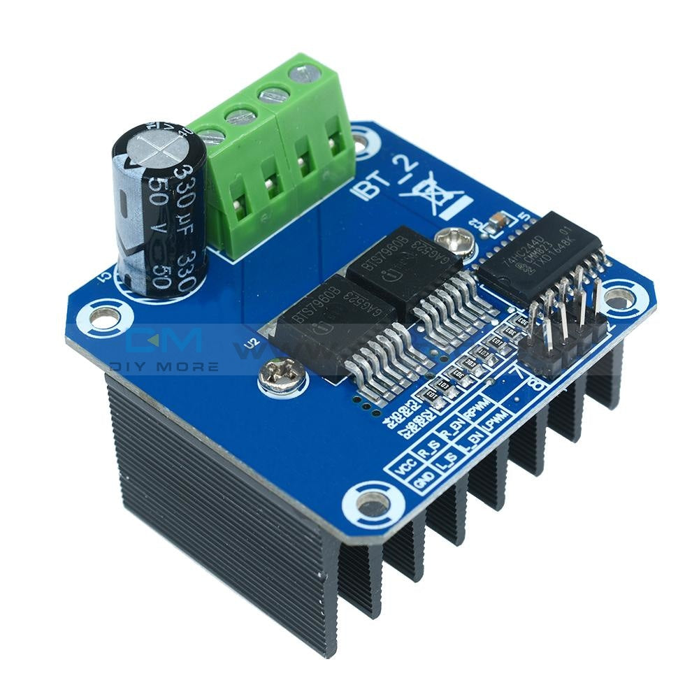
PWM can also be used in general for generating voltages between HIGH and LOW. Arduino PWM output is essential in a number of applications for example in controlling the brightness of a light bulb or controlling the speed of rotation. The RPM of the motor can be controlled by the PWM output. An important application is running motors. This will cause slowly charge, when few first PWM to open highside mosfet with too low voltage Vgs, this can burn up your Mosfet. You will dont need the large boostrap capacitor as 220uF. Arduino Un (Atmega328 MCU) support this mode. In very simple terms, we can output a square wave from certain pins of the Arduino board, and we can control the fraction of time for which the wave will be at the HIGH state (known as the duty cycle). PWM control H-bridge has its technic with complementry output + dead time.


 0 kommentar(er)
